The GIGABYTE X570 Aorus Xtreme Motherboard Review: Fanless AM4
by Gavin Bonshor on September 24, 2019 9:00 AM ESTVisual Inspection
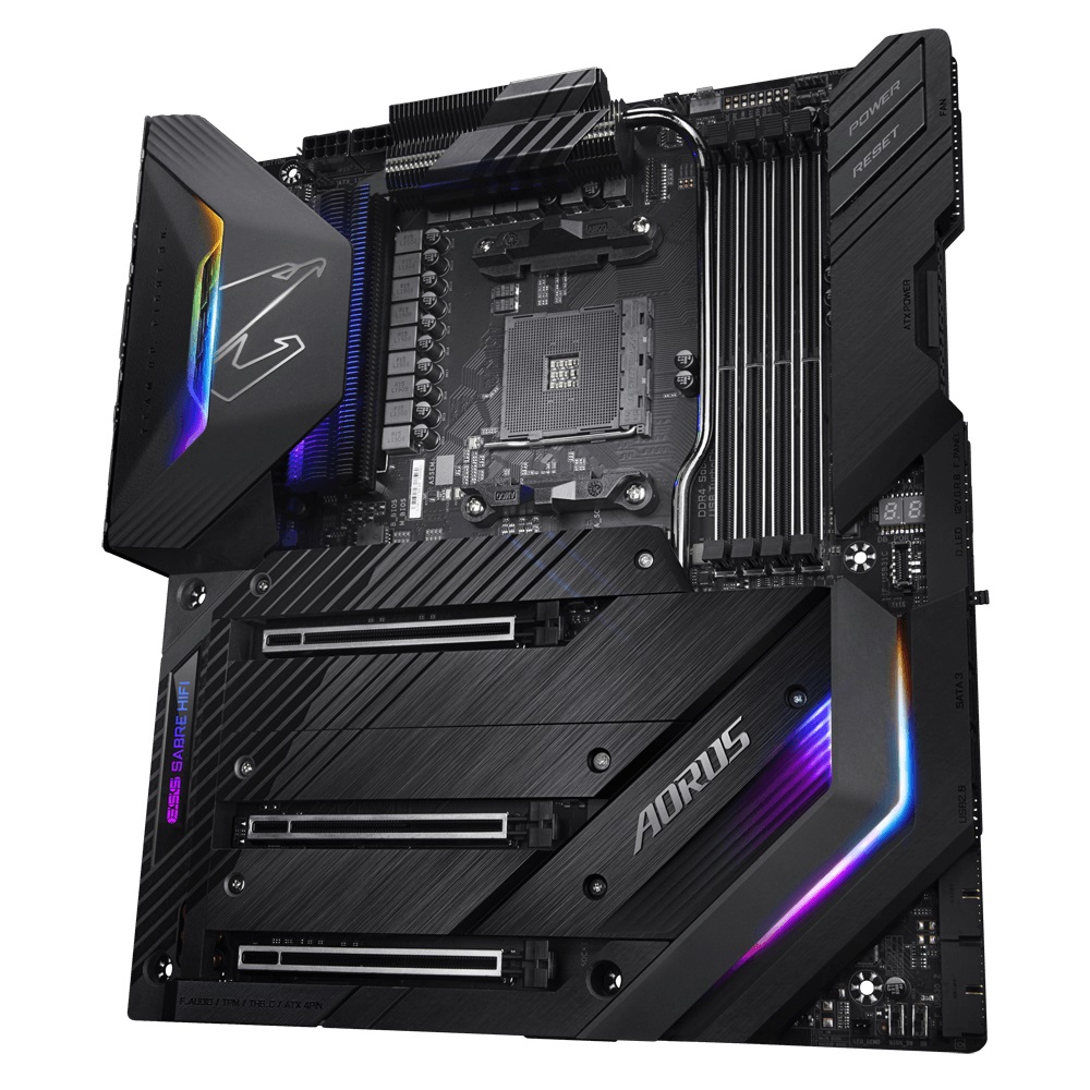
The GIGABYTE X570 Aorus Xtreme is an E-ATX motherboard with plenty of premium controllers and componentry, with a very clean looking and subtle all-black design. It wouldn't be 2019 without multiple areas with integrated RGB LEDs which allows users to create a unique look, or if preferred, users can switch them off altogether. Looking at the general aesthetic, GIGABYTE has gone with an all-black design with its metal thermal reactive armor which covers the vast majority of the rear section of the PCB.
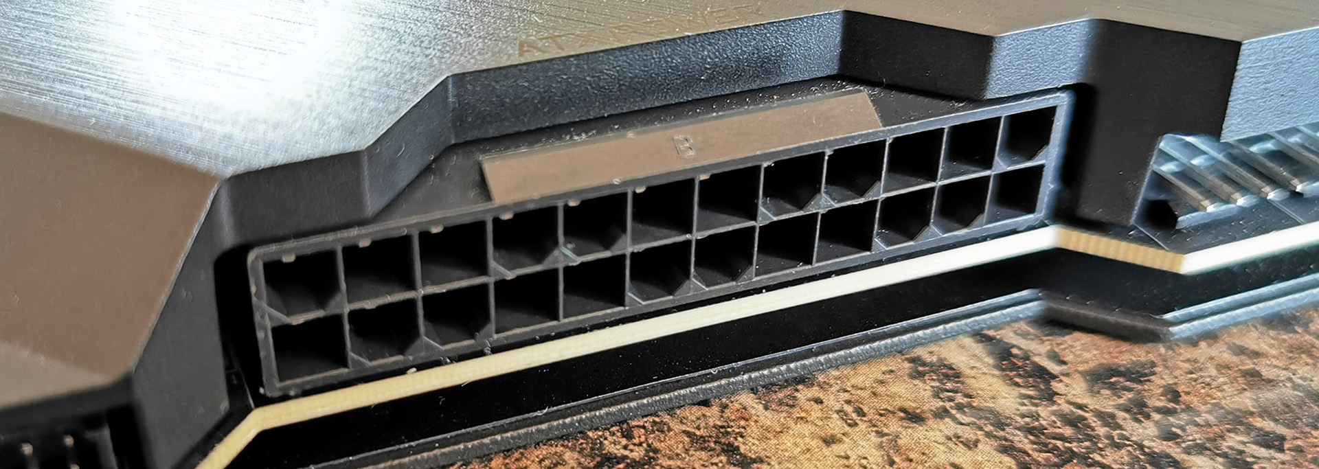
One of the most interesting design implementations on the X570 Aorus Xtreme is the right-angled 24-pin 12 V ATX motherboard power connector which is designed to improve overall cable management, as well as fit in with its clean stylings. Right-angled 24-pin connectors are ultimately nothing new, but integrating it in this way with an 'armor' is different.
Across the board, GIGABYTE has included customizable RGB LED zones which include the rear panel cover, the Aorus falcon branding, the audio PCB cover, and the chipset heatsink. Users looking to expand beyond this can make use of the two addressable RGB headers, with a further two standard RGB LED headers also present.
As the thermal armor covers the majority of the PCB, GIGABYTE has had to get creative with the header placement. In the middle at the right-hand side of the board is a two-digit DEBUG LED which is handy for troubling shooting POST issues, as well as identifying possible overclocking related issues. In the bottom right-hand corner is a dual BIOS switch. As with most overclocking friendly motherboards, the X570 Aorus Xtreme has included a power and reset switch, but unlike the usual bottom-mounted position on most boards, these are located in the top right-hand corner next to the memory slots. Other connectors include a front panel audio header powered by the Realtek ALC1220-VB HD audio codec, eight 4-pin headers which consist of one for a CPU fan, one for a water pump, and six for chassis fans. For extreme overclockers, there is an OC PEG power connector which allows more power to be delivered to the PCIe 4.0 slots.
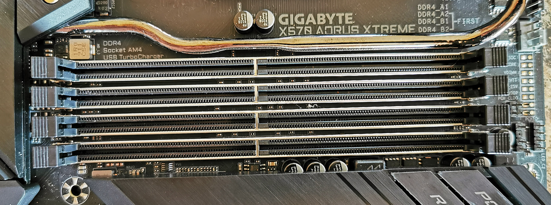
Touching on the memory support on the X570 Aorus Xtreme, there are four memory slots with support for up to DDR4-4400 and allows users to install up to 128 GB. Both the use of non-ECC and ECC memory is supported, but only unbuffered ECC memory is supported.
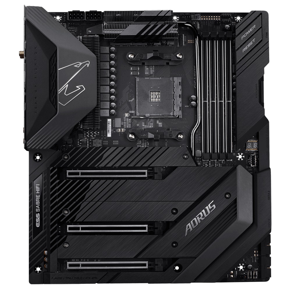
The GIGABYTE X570 Aorus Xtreme uses two full-length PCIe 4.0 slots which run at x16, and x8/x8. There is also third full-length PCIe 4.0 slot fromt he chipset which is locked down to x4. While the board has no PCIe 4.0 x1 slots, its space has been used to include three PCIe 4.0 x4 M.2 slots which also feature support for SATA drives. Each M.2 slot has a separate M.2 heatsink. The top-mounted PCIe 4.0 x4 M.2 slot is driven directly from the CPU, while the other two PCIe 4.0 x4 M.2 slots are controlled directly from the X570 chipset. There are also six SATA ports with support for RAID 0, 1, and 10 arrays, but it should be noted that the bottom-mounted PCIe 4.0 x4 M.2 slot and two of the SATA ports share bandwidth and cannot be used at the same time.
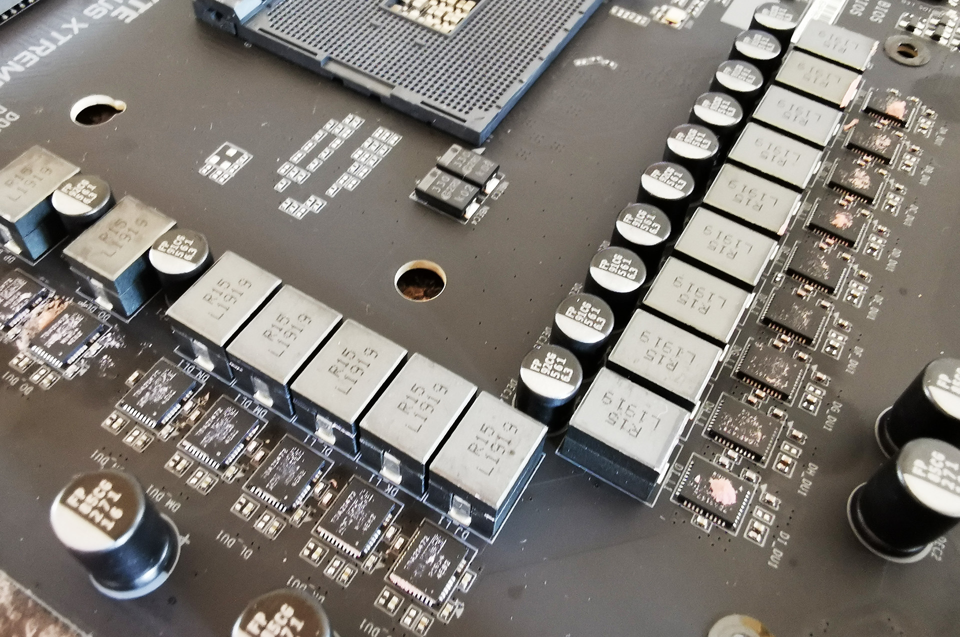
A lot of emphasis on the X570 chipset has been put into its power delivery configurations and when compared with previous generations of AM4 boards such as X370 and X470. In general, vendors have gone with more up-to-date and powerful VRM solutions with these boards expecting to power the 16-core Ryzen 9 3950X when it launches. The GIGABYTE X570 Aorus Xtreme is one shining example of its power delivery implementation, and uses a comprehensive design. The CPU VCore section is using a true 14-phase design with fourteen Infineon TDA21472 70 A power stages. Controlling the power delivery is Infineon's new 16-phase XDPE132G5C digital PWM controller which is operating in 14+2 mode. On the SoC side, the X570 Aorus Xtreme is using a standard 2-phase design which utilizes two TDA21472 70 A power stages. This includes two 8-pin 12 V CPU power inputs which give the CPU extra headroom to draw more power from the power supply when required. The power delivery on the X570 Aorus Xtreme is perhaps one of the best we have seen from a desktop motherboard in recent years and coupled with the impressive power delivery heatsink, this could be the perfect motherboard for overclockers and enthusiasts looking to push the Ryzen 3000 series of CPUs to its limits.
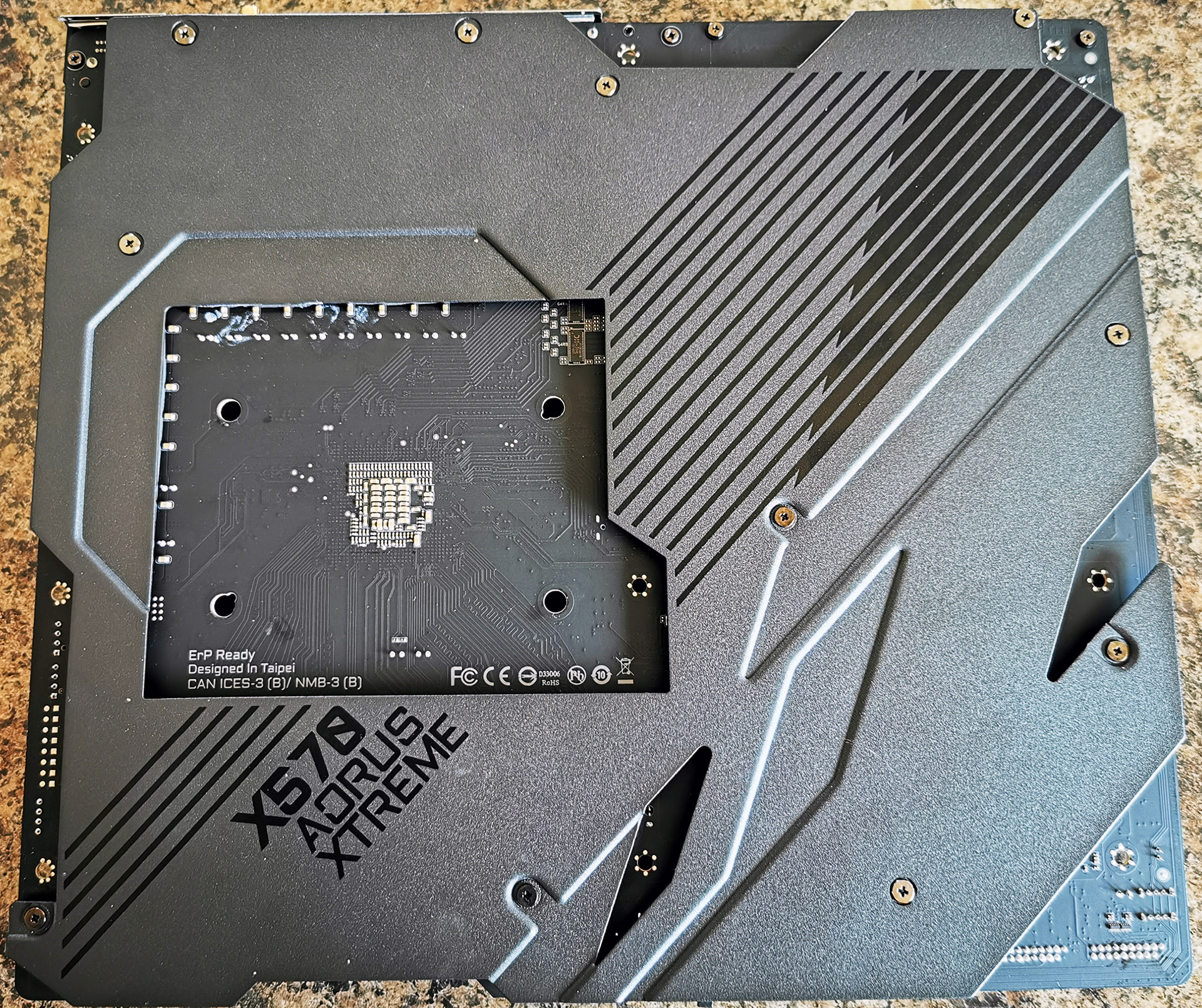
Adding extra to the weight of the nearly all-metal frame of the X570 Aorus Xtreme is a large Aorus branded backplate. Not only is this designed to make the board more durable and add extra reinforcement to avoid PCB warping, but is also designed to provide extra cooling properties. This backplate is coated with a thin layer of nanocarbon which GIGABYTE state is designed to lower backside PWM component temperatures by 10%.
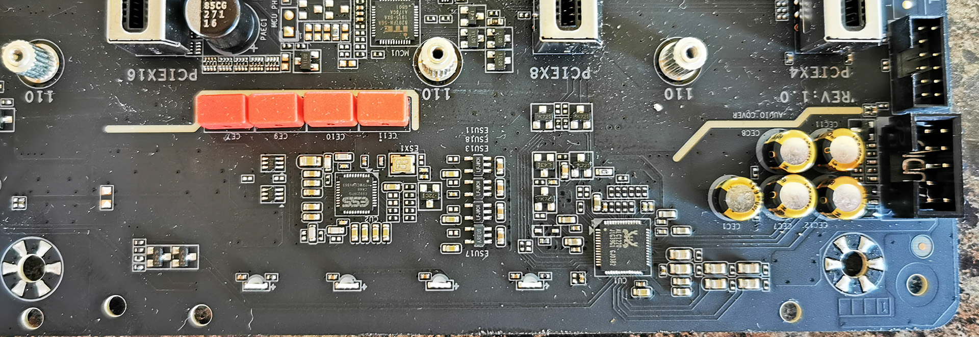
Focusing on the audio PCB, and GIGABYTE as usual with its premium models has provided an upgraded solution which includes basic PCB separation from the rest of the motherboards componentry. The Realtek ALC1220 HD audio codec is assisted by five Japanese gold audio capacitors, while the ESS Sabre ES9218 DAC which enhances the overall quality of the audio up to and including the 130 dB signal to noise ratio it supports. The ES9128 DAC is supported by four WIMA audio capacitors.
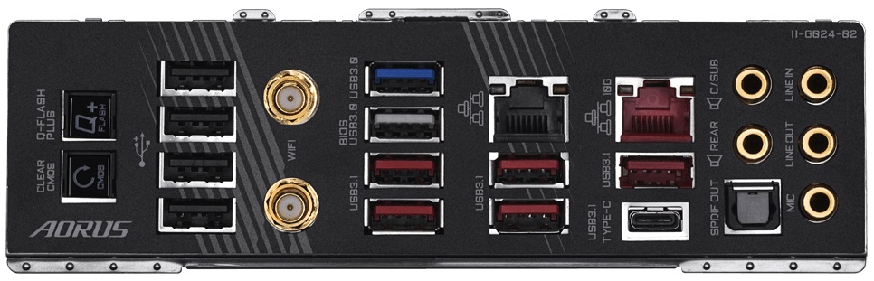
On the rear panel of the GIGABYTE X570 Aorus Xtreme is a varied selection of inputs including an impressive number of USB connections. The X570 Aorus Xtreme features a pre-attached rear I/O shield and includes five USB 3.1 G2 Type-A, one USB 3.1 G2 Type-C, two USB 3.1 G1 Type-A, and four USB 2.0 ports. To the left-hand side is a pair of buttons including a clear CMOS and Q-Flash Plus switch, and there are two antenna ports for the Intel AX200 Wi-Fi 6 802.11ax wireless interface; this also gives users BT 5.0 connectivity. In addition to the Intel AX200 wireless interface is a pair of Ethernet ports powered by an Aquantia AQC107 10 GbE NIC, while the second port is controlled by a basic Intel I211-AT Gigabit NIC. For the onboard audio, there are five gold plated and labelled 3.5 mm audio jacks, with an S/PDIF optical output which are all controlled by a Realtek ALC1220-VB HD audio codec. This is assisted by an ESS Sabre ES9218 DAC.
What's in the Box
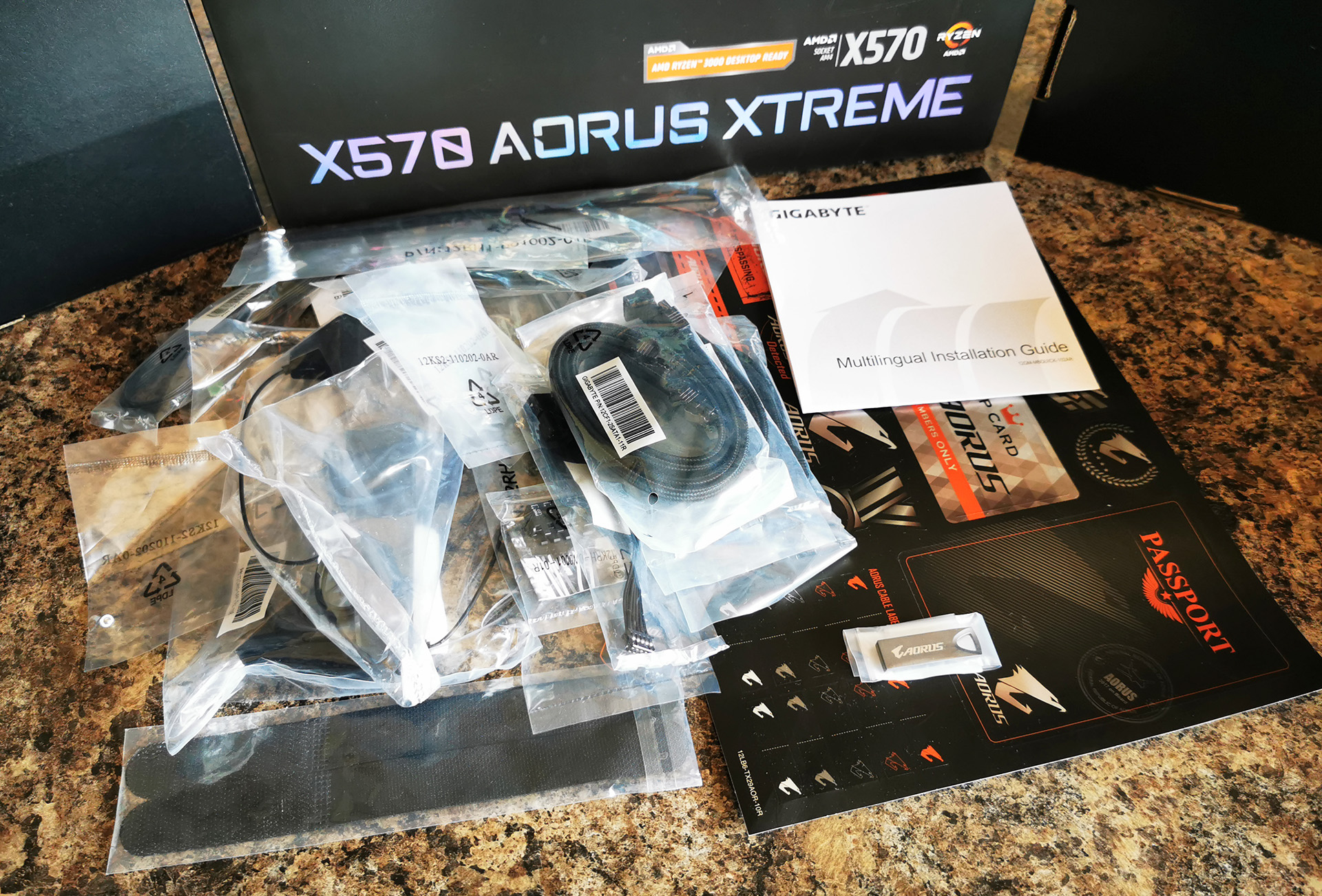
Inside of the large and premium box is a wide variety of accessories and also features the functional Aorus RGB Fan Commander. Also included in the box are six premium braided SATA cables, the Intel AX200 Wi-Fi antenna, two thermal probes, a G-connector, a USB stick containing all of the drivers, a pair of RGB LED extension cables, an audio cable for detecting the dB, a case badge, and a pair of Aorus branded velcro straps.
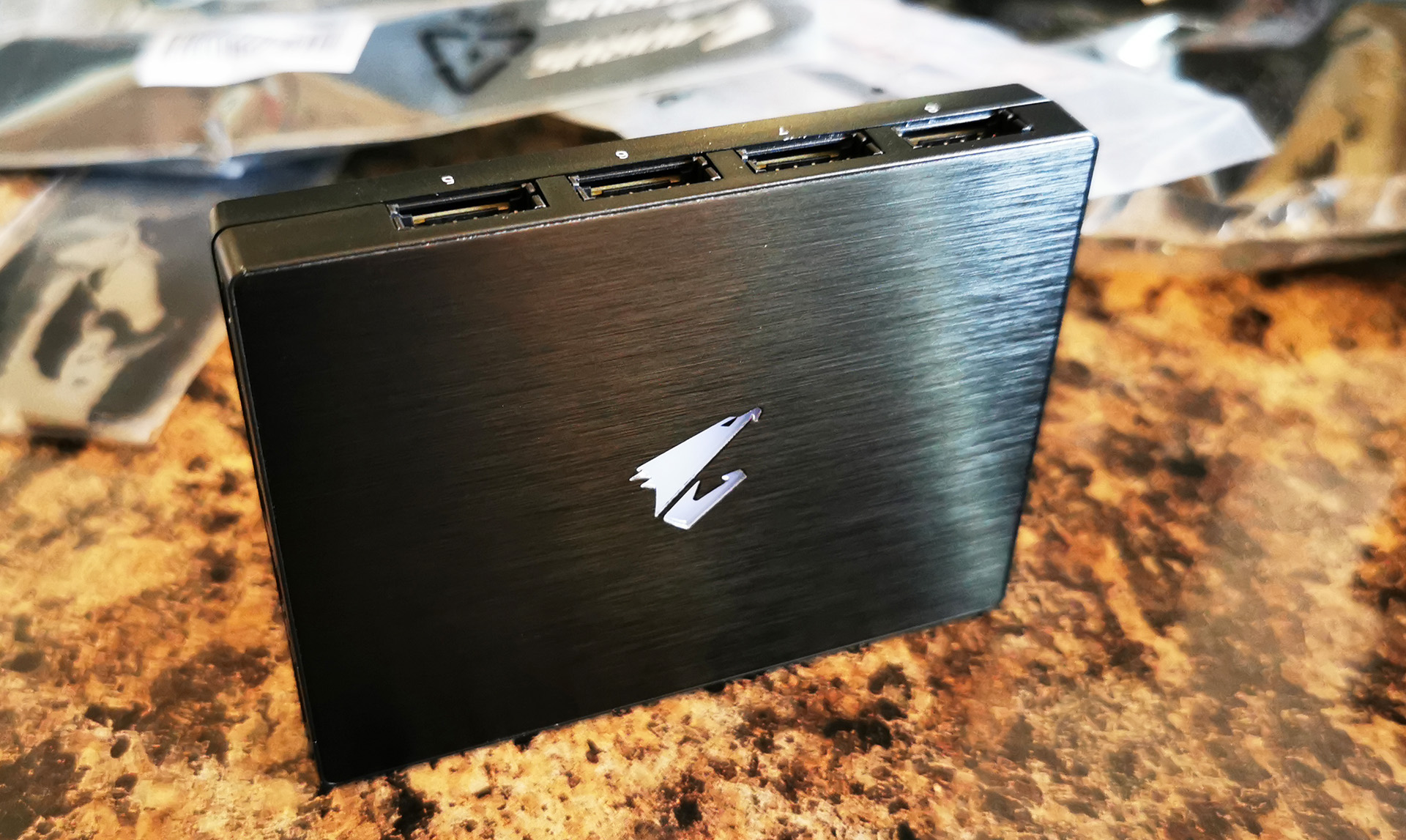
The Aorus RGB Fan Commander comes in a within the packaging and allows users to use up to eight more 4-pin chassis fans with eight separate RGB LED headers via the use of extension cables; these are included in the Commander accessories bundle. With the eight 4-pin headers already available on the X570 Aorus Xtreme's PCB, with the Aorus RGB Fan Commander users can use up to sixteen fans which is great for enthusiasts who want extra cooling options. The Aorus RGB Fan Commander comes supplied with its own plethora of cables including RGB LED splitter cables for RGB fans, and extension cables to connect 4-pin fans to the Commander itself.
- 6 x Black braided SATA cables
- RGB LED extension cable
- ARGB LED extension cable
- Intel AX200 antenna set
- 2 x Thermal probes
- Aorus RGB Fan Commander
- Installation manual
- Quick Start Guide
- 3 x M.2 Installation screws
- USB Driver/Software installation drive
- Front panel G-Connector
- Front Panel splitter cable


42 Comments
View All Comments
Smell This - Tuesday, September 24, 2019 - link
Maybe __ but I'm not sure I get your point.A conventional top down plugin has to bend 180-degrees to route under the tray as opposed to a 90-degree 'bend' ??
DanNeely - Tuesday, September 24, 2019 - link
A 90* plug doesn't get you anything unless you're routing the cable on the same side as the board (which isn't normal these days outside of SFF), or can make a tight 90* bend as the cable comes out of the routing hole. Unless you have a really flexible cable you're not going to be able to do that. Instead you end up having to make a 270* loop (up, then forward into where drive bays used to be, and then down and back to the board), so you still end up with a big loop.With a big loop a 180* can be done without putting any bending stress on the plug. A 270* either needs more cable to match the same bending radius or will have to be tighter and puts more stress on the board as a result. With the one system I had this sort of setup in there wasn't enough slack in the cable to do a loop with enough slack that it wasn't trying to bend/twist the board up. When I plugged the cable in before the board was screwed down it was flexing the board up when I tried screwing it down on the edge with the socket. With the board screwed down first, it was very difficult to get the plug to the socket partly because of the tray meaning I could only grip the cable from one side and partly because the cable didn't want to be bent tightly enough to go in. On the whole it was among the most frustrating build steps I ever did and the stiffness of the cable meant that it completely failed at the notional goal of keeping the wires out of the way that's normally behind 90* edge plugs.
My initial thought was that a rigid 90* adapter that extended out to the cable management hole would avoid the problem by removing the need to tightly bend the cable to fit. Thinking a bit more, that probably wouldn't be enough because making a tight bend behind the board would be just as difficult; you'd either need a 180* piece so the cable could stay flat on the backside of the board, or a short extension with all loose wires to make it work.
Ratman6161 - Tuesday, September 24, 2019 - link
How about this:https://www.newegg.com/cooler-master-cma-cemb00xxb...
Ratman6161 - Tuesday, September 24, 2019 - link
https://www.google.com/search?q=ATX+24+Pin+90%C2%B...MamiyaOtaru - Wednesday, October 9, 2019 - link
cool, connect that to the side plug and come at it from behind /seek2121 - Tuesday, September 24, 2019 - link
IMO we need a better solution for all the connectors that exist on motherboards. For example, those USB3 connectors. How many times have I bent a pin trying to plug one in when it accidentally gets pulled out? More than I'd care to admit. I mean hell, at least put a snap/latch on it similar to what most SATA cables have. Ideally, we've had 1 cable running from the case to the motherboard, and 1 cable running from the PSU to the motherboard. Both connectors would had the little snap or latch or whatever you call it, and both would be right angled so that they can easily be hidden from view for a nice clean look.DanNeely - Wednesday, September 25, 2019 - link
USB-C does use a smaller and more robust connector than USB 3.0 (you can see one on this board near the diagnostic code display) that appears to take its design inspiration from PCIe.A single cable from the PSU to the mobo would run into one size fits all problems and end up huge, ex the difference between the needs of an SFF system using a 4 pin CPU header and a high end work station/gaming board using 2x8pin CPU headers and a PCIe header (to give extra power for multiple GPUs).
What could be done easily enough would be to gut the 24 pin cable by making about half of its wires optional; even if not followed up by a new smaller plug/socket a few years later it would remove a lot of the headaches from the worst connector on the mobo. This could be done safely because the original 20 pin connector dates back to when the CPU ran on 3.3v, everything else ran on 5V, and hardly anything needed 12V; vs today when 5V is used almost exclusively for USB, 3.3V for odds and ends (eg 10 of the 25/75W a PCIe card can draw from the mobo is 3.3v not 12v), while everything else runs 12V to component specific voltage regulators.
The reason nothing's happened is more or less the same as why the mess of jumper style headers for the front panel has never been replaced by a standard block style connection. The PC industry as a whole no longer cares about desktops enough to expend the effort needed for a major new standardization round. Big OEMs can and do address the issues via proprietary components scoring spare part lockin as a bonus; while for everyone else (eg the people who make parts for customer built systems/boutique vendors) the upfront time spent and short term costs from needing to bundle legacy/modern adapters for a few years is too high to try and push something on their own. Residual trauma from the effort spent on the failed BTX standard some years back was probably an issue back when desktops were still important enough of a market segment to get serious engineering effort in standard modernization as well.
Dug - Monday, October 7, 2019 - link
I just have to chime in and agree with changing the entire layout. Look what oem's can do when they aren't tied to the ancient atx power supply and standard pin layout. Look at the power supply used on an imac pro. That's how it should be done. These giant cables and connectors are really unnecessary.4everalone - Tuesday, September 24, 2019 - link
I wish MB makers would start providing SFP+ ports instead of 10GBASE-T ports. That way we at-least have the option of running fiber/copper.TheinsanegamerN - Tuesday, September 24, 2019 - link
I like the look of the board and passive X570 cooling, but am dissapointed at the lack of expansion slots. No USB 3 header? Really? Just a gen 2 that cant be used on the vast majority of cases, and even if it can it will onyl feed a singular port? No PCIe x1 slots for, say, a USB 3 header card to make up for the lack of internal headers?Granted, this is a subjective problem, not many people use more then 1-2 slots, but for the price, I would want way mroe expansion for future upgrades. Think USB 3 headers, replacement NIC or sound cards in case of on board failure, NVMe cards for RAID arrays and better cooling, ece.