Texture Mapping Basics
The most noticeable improvement
Perhaps the most noticeable image quality improvement ever is texture mapping. Prior to texture mapping, single colored polygons and lighting could emulate smooth surfaces quite well; however, texture was missing in these games. It was very difficult, or impossible to give the player a feeling of navigating through a real world with brick walls, wooden floors, grass, and more. Texture mapping allows game developers to map a "texture" (an image) onto a polygon. This way, what once was a brown square can transform into a square with a stone texture, so it would look like it is made of stone, or a square with a sign texture mapped on it. Well, you probably know what texture mapping is so I won't bore you with any more details...
Linear texture mapping
The first texture mapped games (Ultima Underworld, Magic Carpet I) did something called "linear texture mapping". This texture mapping method worked well for polygons which were facing the player directly, and those which were far away; however, when you got closer and closer, the polygons became severely warped. The reason for this is that when they went through the rows and columns "choosing" the coordinate in the texture which to draw, these games did not take the polygons 3D attributes into consideration. This type of texture mapping is unacceptable in today's games. I don't believe ANY 3D accelerator EVER used linear texture mapping.
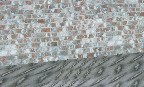
Notice the texture warping on the floor underneath the brick wall.
Perspective Correct(ion)
How was this problem fixed? Well, the polygons 3D attributes have to be taken into account. Perspective Correction is a somewhat difficult technique to understand, so I will explain it in a different article coming soon... Briefly (VERY briefly) Perspective Correction projects the Texture X and Y coordinates before interpolating them across the polygons rows and down the edges, "unprojecting (multiplying by Z, or dividing by 1/Z" the X,Y coordinates (to get the real texture coordinate) and then draws it. What?! Don't worry, you aren't supposed to understand it... Just know that all 3D accelerators have Perspective Correction; actually, technically speaking they produce perspective CORRECT images (perspective correction implies that the "true" texture X,Y coordinates are calculated every x number of pixels, and then the polygon display function linearly interpolates (i.e. adds a step value) to find the next pixel) Anyway, perspective correction is a given nowadays.
Point Sampling
Recall I spoke about "multiplying by Z", "interpolation (adding step values)" etc.? Unfortunately, we can only plot whole point coordinates, so even though our Z values may have decimals, and our step values may be fractional, we can only plot whole points. This causes visual anomalies because we are never actually plotting the correct pixel. Point sampling is the process of selecting the nearest whole value texture coordinate to display. This is the simplest, fastest, and ugliest way of choosing the pixel to draw. This is the method most software renderers use (up until Unreal)
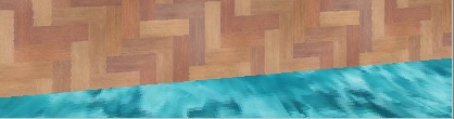
Notice the pixelation at the bottom right corner. Since point sampling sometimes chooses the same point over a few times, pixelation occurs. Also notice some jagged edges in the wooden "wall". (Again, snapshot taken from my 3D engine) Notice that these images are perspective correct. (No, I didn't come up with some ingenious algorithm for doing true perspective correction, I do the good old 2 fixed point! (haha, you can't get any slower than that!) divisions per pixel). Notice that the pixelation in this image is probably less than what you will get with other point sampling engines because (a) The original images are pretty smooth (b) The textures are 256x256 (c) The "water" (Hey, its better than the quake water :) is relatively far away.
Anyway, enough talking about outdated techniques, lets get on to the current method of selecting pixels. (well, relatively current)
Bilinear Filtering
What does bilinear filtering do? Well, bilinear filtering is a weighted average of the colors of the 4 nearest pixels to the actual location. Pretty simple huh? Unfortunately, it is also pretty slow... This technique is almost solely restricted to hardware 3D because it is extremely slow to implement in software. (~ 12 multiplication's and 4 additions, when using true color modes) As you can see from the screen shot below, bilinear filtering "smooths" images, sometimes a little too much.
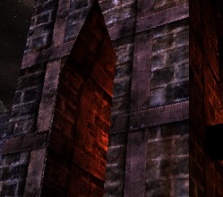
It's somewhat dark, but you can probably tell that the bricks and textures are "smoothed". This is the outcome of bilinear filtering. (I won't say that this IS bilinear filtering because I am not sure if Unreal's software renderer does "real" bilinear filtering. It seems to me as if they cheat a little)
Where does the name bilinear filtering come from anyway? Translating bilinear you get something like "two lines", or "in two lines", or possibly "two dimensional". This means that bilinear filtering samples (chooses) the best pixel by blending in two dimensions, i.e. it blends the closest to texture coordinates on the X coordinates with the two closest on the Y coordinates, as opposed to simply performing a weighted average on the two X-coordinate pixels (i.e. texture coordinate 2.3,2.3 would be rounded to 2.3,2 and then they would take a weighted average of the points 2,2 and 3,2; instead of taking a weighted average of the points (2,2), (3,2), (2,3), (3,3). Bilinear filtering is probably the most noticeable image quality improvement that comes with 3D hardware.
Even though bilinear filtering is great, it has it's shortcomings; most noticeably, the "texture sparkle" effect which is very common. I would have given you a snapshot but its only really noticeable in motion, and I don't want to make an AVI...


0 Comments
View All Comments